Aristotelis Economides,
Binu Amaratunga,
Carme Homs Pons,
Edrick Solis Gonzalez,
Rebekka Karrer.
under supervision by
Dr. rer. nat. Christoph Kowitz
Dr.-Ing. Petar Tzenov
Friedrich Menhorn, M.Sc. (Hons)
The Honours Project was completed at the Chair of Computational Modeling and Simulation and was supervised by Tim Bürchner, M.Sc.
Almost every digital device such as computers, smart-phones, refrigerators, and cameras are based on one or more ICs. Many technological advances of the past decades have only been possible because of the developments of ICs which provide compactness, reliability, power saving, and performance. The design of a new IC poses a huge challenge because thousands, or millions, or even billions of different semiconductor devices not only should function as expected but also should fit into a piece of silicon of several millimeters of dimensions and function without being affected by electromagnetic interference or excessive heat.
Because the process of fabrication of ICs on a block of semiconductor material (called a die or wafer) is extremely expensive, it is important to verify the functionality of the IC before going into fabrication. Therefore simulation for verification at many levels of the IC design process is extremely important. Analog Circuit Simulation, which is the focus of this project, is done at two instances of the design process; after the initial circuit level schematic has been designed and after the circuit layout has been done.
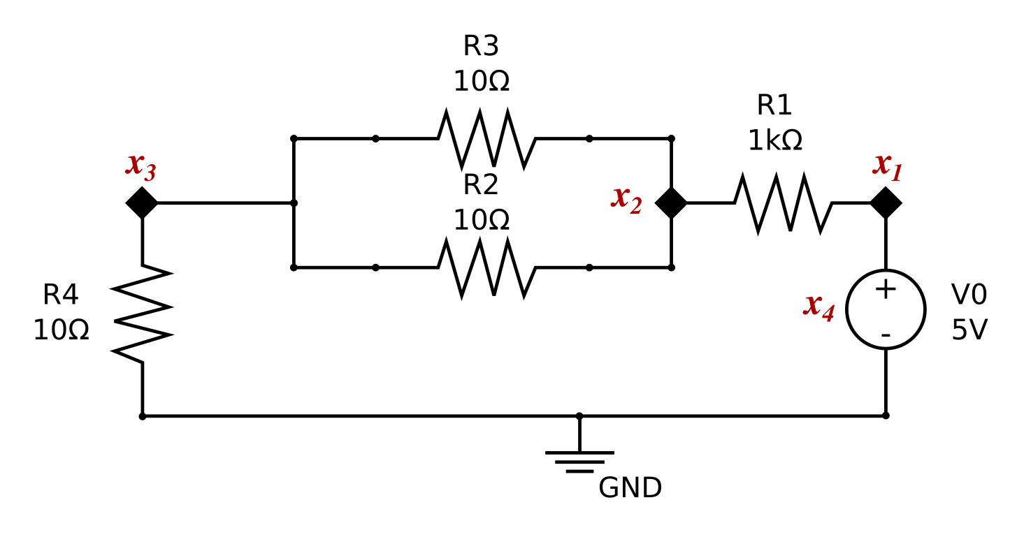
Fig. 1: Sample Circuit
The goal of this project is to implement a novel in-house circuit simulator for Infineon Technologies AG, one of the ten largest semiconductor manufacturers in the world. The new circuit simulator, programmed from scratch, has incorporated state-of-the-art programming techniques and APIs. Due to the complexity of the simulation tool chain, modularity of the software design is important for ease of maintainability. In order to be able to simulate circuits in the order of millions of components each and every component needs to be linearly time scaling and efficient. Therefore both modularity and efficiency have been considered throughout the design and implementation of the circuit simulator.
The circuit simulator consists of three main components: the netlist compiler, the intermediate representation, and the analysis kernel.
The netlist compiler is the component which receives the circuit netlist as an input, whereby a netlist is a representation of the circuit written using a hardware descriptive language such as TITAN or Spectre. The netlist compiler consists of three main components. The code related to Compiler Grammar, the code related to conversion to Intermediate Representation, and the code related to Semantic Analysis. The Compiler Grammar has been written using the PEGTL (Parser Expression Grammar Template Library) Library which is a header-only C++ library. The next component which is the Intermediate Representation (IR) acts as a bridge between the compiler (frontend) and the kernel (backend). It is a data structure responsible for communication between the two components as it is designed such that both components can handle the data effectively. Simultaneously, it is an integral part of the compiler because the IR is modified multiple times between the initialization and the passing of the IR to the kernel. These modifications serve several purposes such as name resolution and optimizations which belong to the Semantic Analysis phase. All three phases of our netlist compiler implementation show linear time complexity.
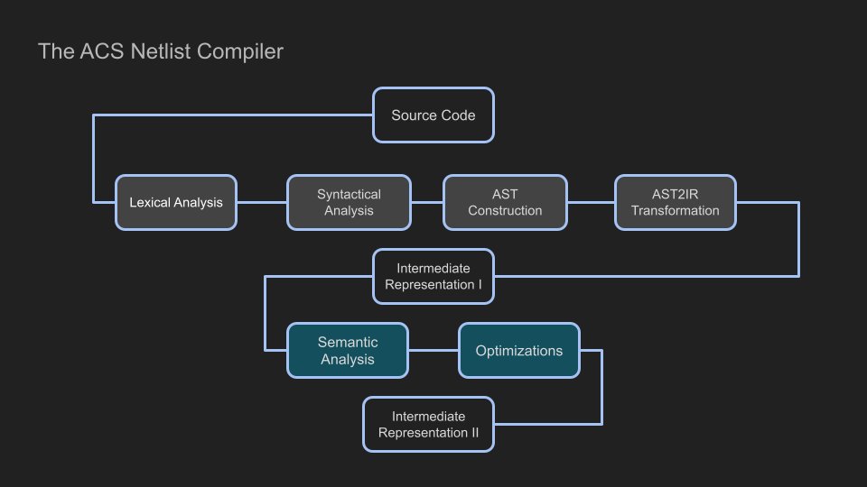
Fig. 2: ACS Netlist Compiler Workflow
The Analysis Kernel part of the solver is the one responsible for the circuit analysis. In circuit analysis, the goal is to find the output signals without actually measuring them. To do so, we formulate and solve a system of equations that fully describes the behavior of the circuit. To formulate the equations of the circuit, information not only about the input signals, but also about all the present devices and their connectivity is needed. The system of equations that describes the circuit is not unique and different unknowns can be considered. Choosing a suitable method is a key factor in circuit simulation. During the last decades, the Modified Nodal Analysis (MNA) has emerged as the method of choice which we have used in our Analog Circuit Simulator.
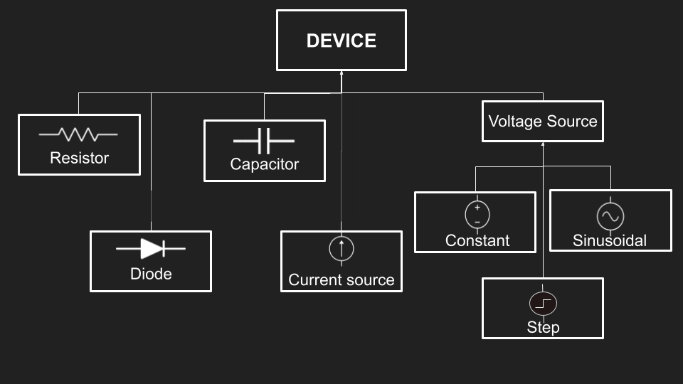
Fig. 3: Kernel Class Structure
The simulator currently supports operating point (OP) analysis and transient analysis. The difference between OP and transient analysis, is that the OP analysis calculates the state of the circuit at a single time point while the transient analysis calculates the state of the circuit across a time interval. Both of them call the ‘Newton’ method to solve the MNA equations for every point in time. The analysis kernel first converts the information from the IR to a setup which is then used to solve the appropriate equations. Depending on the required analysis type, different discretization schemes and solvers are selected and the system of equations are solved.