Chunxiang Huang
Huang did her honours project at the Institute for Machine Tools and Industrial Management (iwb), supervised by Dipl.-Ing. Christian Seidel and Prof. Dr. Fabian Duddeck.
Background
Laser beam melting (LBM) process is a type of additive manufacturing technology, in which a laser beam selectively melts a metal powder bed layer by layer to form a three dimensional geometry. This technology provides much freedom in part design and can be used to develop light-weight optimized geometries. The accuracy and microstructure of the parts depend on the following machine parameters: beam power, scan speed, hatch pattern, recoat time, layer thickness and etc. These parameters have to be studied and optimized in order to obtain a part with higher accuracy and less distortion. The Institute for Machine Tools and Industrial Management at TUM is currently developing a simulation tool to analyze the whole LBM process for this aim. This tool uses ANSYS APDL for simulating the thermo-mechanical behaviour of a part being built layer by layer. The input geometry in this tool can be created based on the information from the CLI file, containing the coordinates of all points on each layer. And the mesh will be generated automatically using a maximal element size as constraint. Often, a small element size is used in order to capture all the details in the part, which is unnecessary for the massive area and increases the number of elements, thus increasing the calculation time. To attack this issue, a program to pre-process the CLI file is developed, so that the part is subdivided into filigree and massive parts and different element sizes can be applied to them.
CLI File
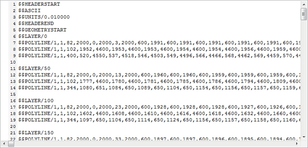
CLI (Common Layer Interface) is a file format for the input of geometry information used in most of the additive manufacturing machines [2]. In this project, we used the software Magics to generate a CLI file from the STL file and converted it to ASCII format with the EOS RP-Tools to make it more readable. The following is an example of such an ASCII CLI file, containing information of layer thickness and coordinates of points on each poly-line.
Program to Detect the Filigree Area
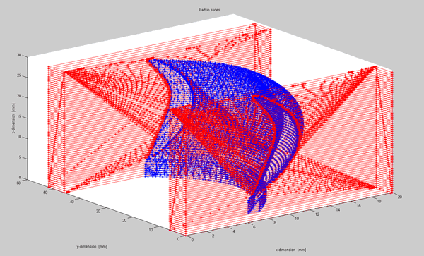
An EXE tool to detect the filigree area was developed with C++ language. One can drag a CLI file and drop to the EXE tool to start running the program and a pile of PRN files will be generated automatically based on some user input parameters. The output files Ebene_i.prn can be used in ANSYS to reconstruct the whole part geometry layer by layer (http://www.dgm.de/download/tg/1171/1171-217.pdf). An alternative is to use the Ebene_f_i.prn and Ebene_m_i.prn to construct the filigree and massive areas separately so that different mesh element sizes can be applied. Furthermore, some MATLAB scripts are written to plot the part and one can visualise the massive and filigree parts with different colours. The following figure is such an example: the blue area is filigree and the red area is massive.