Iñigo López
Iñigo López did his honours’ project at Airbus Defence and Space in cooperation with the Chair of Structural Analysis (TUM) and the International Center for Numerical Methods in Engineering. He was supervised by Stepan Rechtik M.Sc., Dipl.-Ing. Roland Wüchner and Prof. Dr.-Ing. Kai-Uwe Bletzinger.
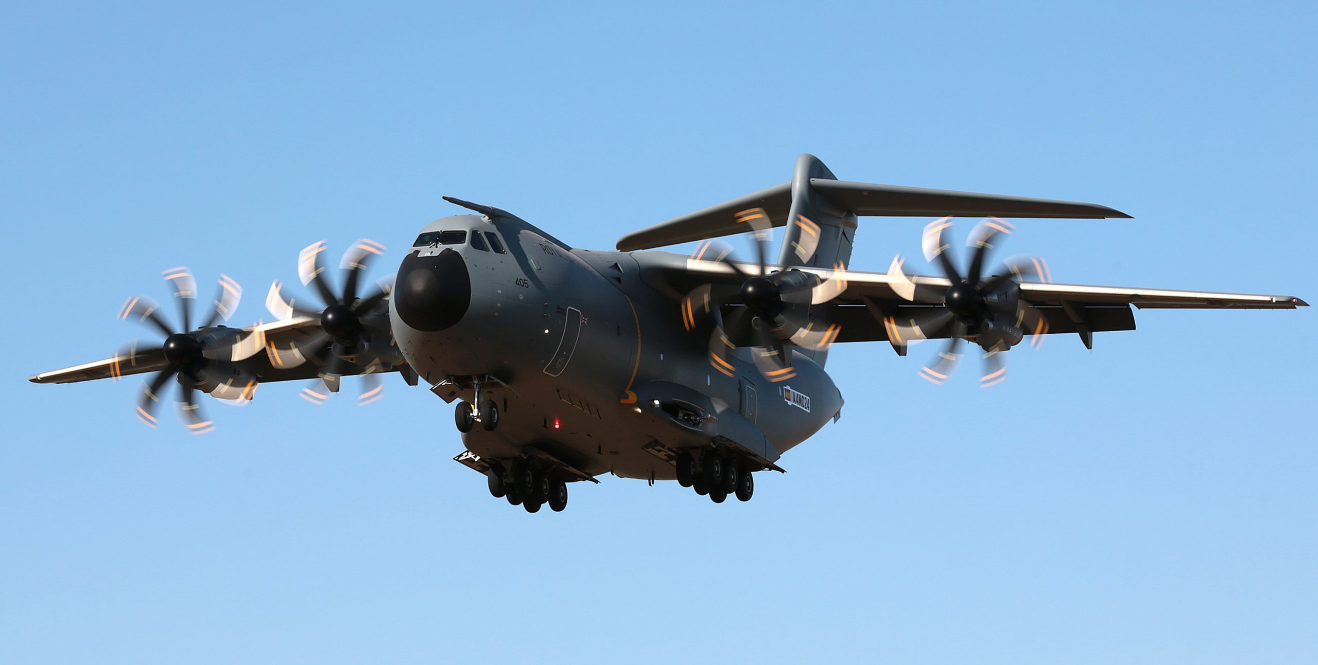
In the context of the aircraft industry, aeroelastic optimization is used to perform flight-load-design. This allows to find optimal aircraft designs that meet structural, economic and safety constraints (Figure 1). A few optimization examples are the maximization of lift and speed, or the minimization of weight, drag and fuel consumption. The optimization process requires computing the aerodynamic loads acting on the aircraft. The aim of this project is to develop a fluid solver that computes the air flow around an aircraft in order to calculate the aerodynamic loads.
Fig.1: Aeroelastic optimization has allowed Airbus to develop the A400M
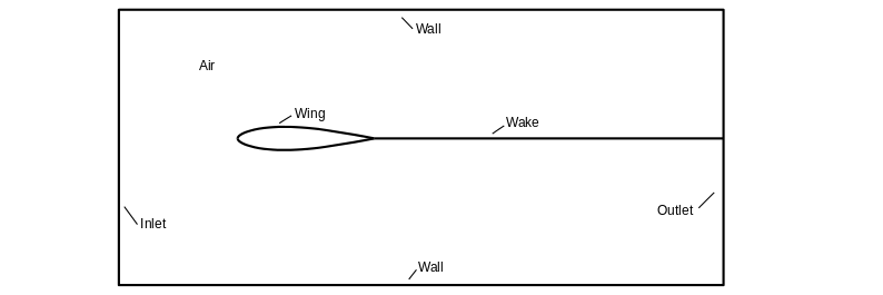
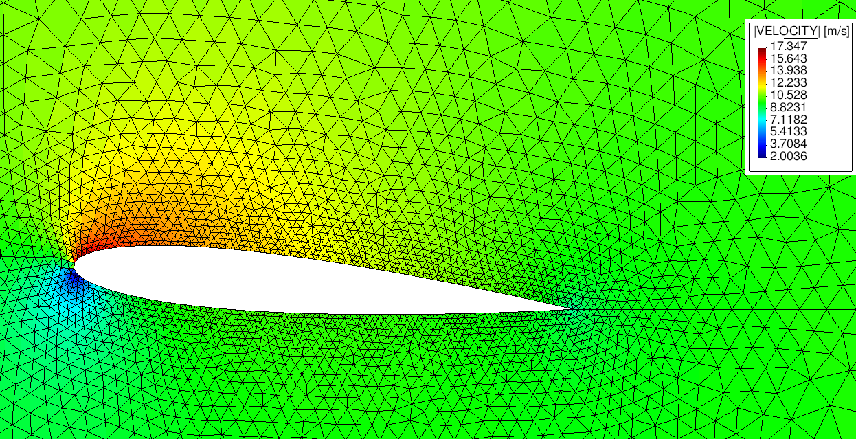
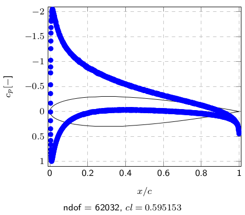
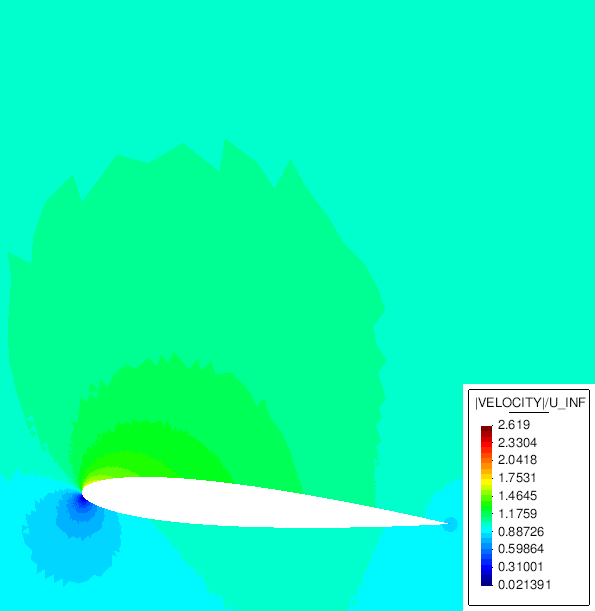
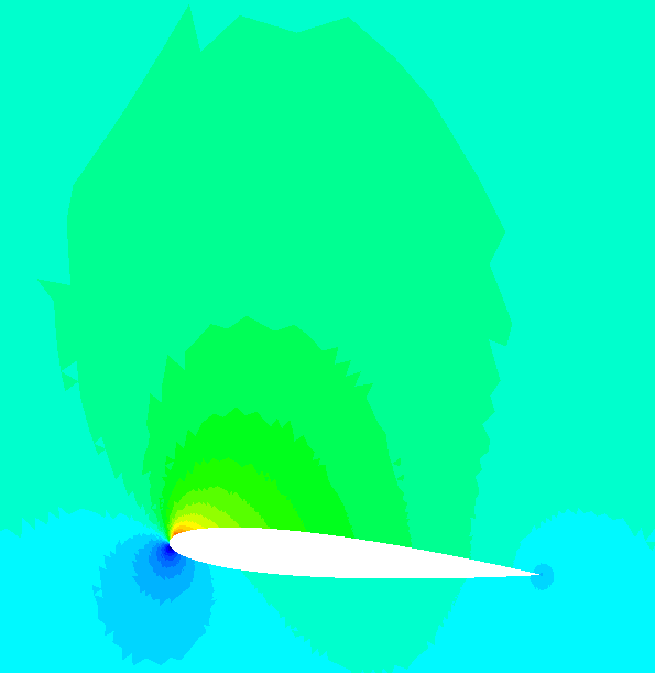
Nowadays, state-of-the-art fluid solvers require a large amount of design variables and system evaluations to achieve accurate results. This leads to a significant overhead. For this reason a full-potential solver was developed in order to reduce the computational cost without loss of accuracy. Fast and robust subsonic solutions to the full-potential equation were obtained by means of the finite-element method. Figure 2 presents a sketch of the fluid domain and its boundaries. Figure 3 shows the solution for a NACA 0012 for an angle of attack of 5°. The resulting pressure distribution along the airfoil is presented in Figure 4. The wake boundary conditions were applied using a least-squares finite-element approach.
Fig.2: Fluid domain and its boundaries
Fig.3: Numerical solution of the velocity field around a NACA 0012 at 5°
Fig.4: Pressure coefficient distribution along the chord
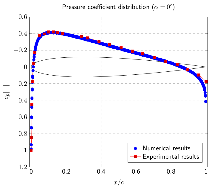
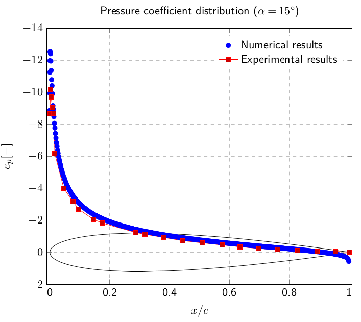
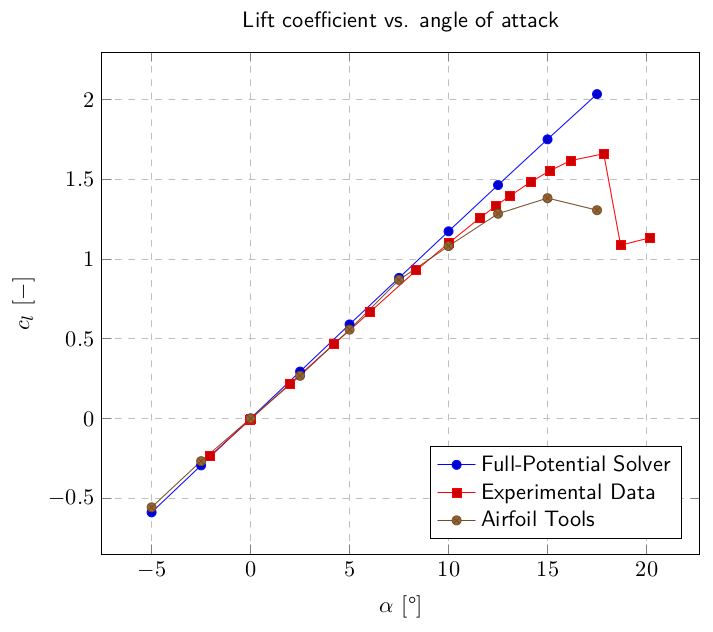
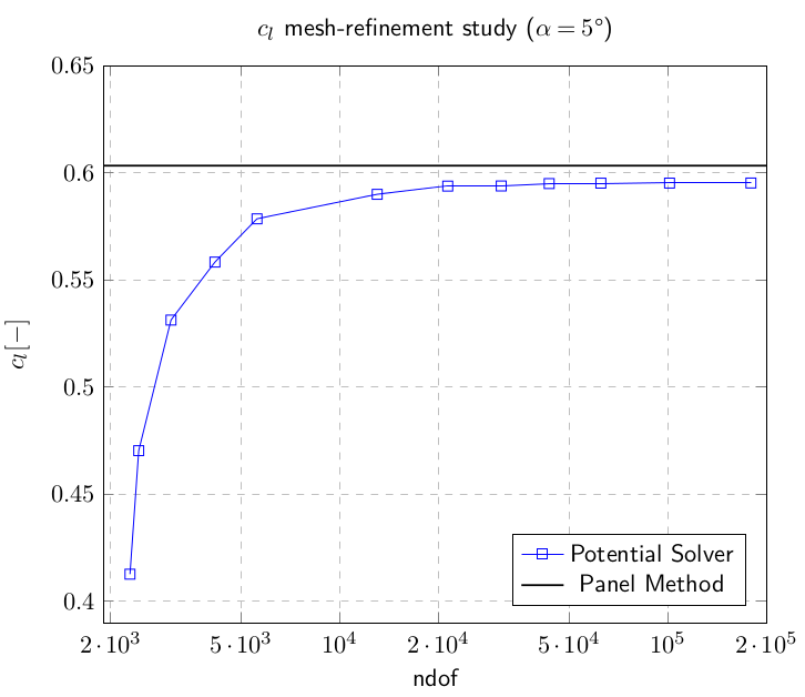
The full-potential solver is implemented in Kratos Multi-Physics, an open source framework to develop multidisciplinary programs. Efficiency is achieved using Kratos’ object-oriented data structure. Validation and verification of the solver were performed for a NACA 0012. Mesh-refinement studies show convergence of the solution for an airfoil element size 1000 times smaller than the chord. Domain size studies suggest that the far-field boundary conditions should be applied at a distance 50 times the chord (Figure 5). Comparison between numerical and experimental results present an accurate matching for small angles of attack, where the boundary layer is attached (Figures 6 and 7). For high flight speeds, Figure 8 shows the dilatation of the flow pattern due to the large density gradients. Approaching transonic flows the problem becomes hyperbolic and the Jacobian is ill-defined. In this flight range further stabilization techniques are necessary to apply the finite-element method. A modification of the isentropic density relation proves to enlarge the range of application.
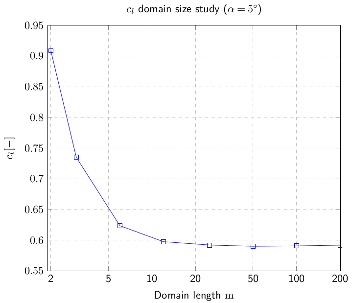 |
Fig.5: Mesh-refinement and domain size studies showing the convergence of the lift coefficient
Fig.6: Validation of the pressure coefficient distribution along the chord
Fig.7: Validation of the lift coefficient for small angles of attack
Fig.8: Dilatation of the flow pattern due to the high velocities
References
| [1] |
Eller, D.
Fast, Unstructured-Mesh Finite-Element Method for Nonlinear Subsonic Flow.
Journal of aircraft 49 (5), pp. 1471-1479, 2012. |
| [2] |
Drela, M.
Flight Vehicle Aerodynamics
The MIT Press, 2014. |
| [2] |
Nishida, B.
Fully Simultaneous Coupling of the Full Potential Equation and the Integral Boundary Layer Equations in Three Dimensions
Massachusetts Institute of Technology, 1996. |